
When sector count=64, only half of the flash space will be used. One clarification for my earlier response about Override File sector_count = 64, the total sector count for S25FL064L is 128. This is expected result as the flash won't respond at all due to the incorrect timing. It just shows the error message that flash is not found. The attached log doesn't mean that it is recognizing the commands correctly. Not only Cypress flash but also other vendor's SPI flash won't work with this timing (i.e., CS not raising at multiple of 8 clock cycles). You may have to contact Intel to help on this issue. However, we don't have the access to the Intel/Altera SPI Controller IP and not able to debug. This issue might come from SPI Controller IP. The app note describes the configurations required for Cypress flash.
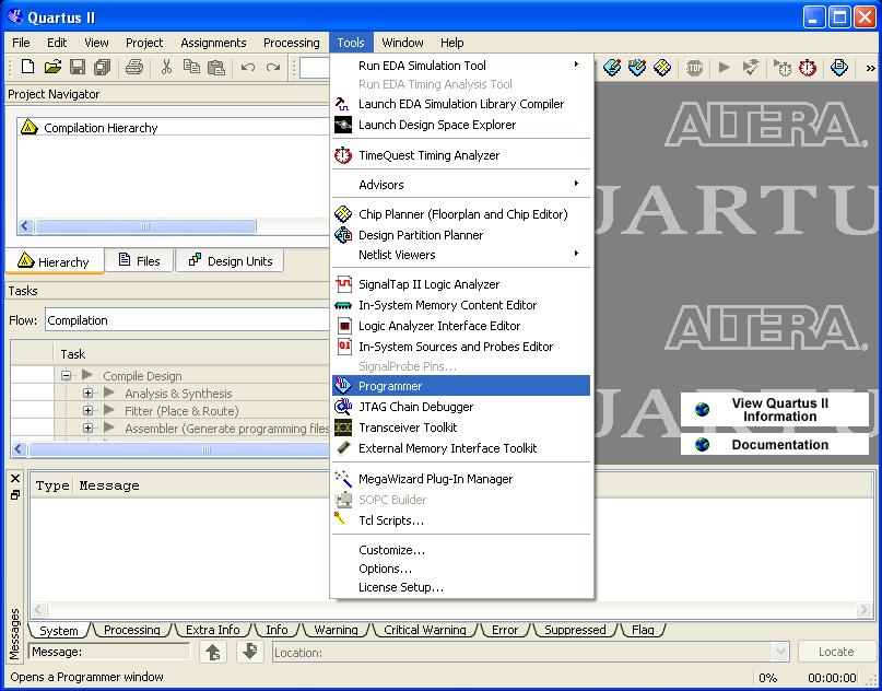
ALTERA QUARTUS II 13.1 PROGRAMMER VERIFICATION
The verification and app note is done based on Intel/Altera SPI Controller IP. I talked with our Application Engineer who did the verification and wrote the app note. The sector count is the half of the total count. "The main Flash array is divided into uniform erase units called physical Blocks (64 KB)". The sector size in the datasheet is described in section 6.2:

The steps in the app note do not have any configuration for this. I believe other vendor's SPI flash devices have the same requirement. As this (CS raising at multiple 8 clock cycles) is the requirement from SPI protocol.

You may need to check the SPI controller. Adding pull up on CS line will not fix this issue. They are sent/controlled by SPI flash controller. Incorrect Power On Reset timing could cause the flash malfunction.īoth CS and CLK signals are input signals for flash. The purpose of adding pull up on CS line is to make sure the flash Power On Reset timing is satisfied so that the flash can be initialized properly during power up. CLK (raising after 9th clock) are two different issues. When create the Override File for Nios II (section 3.2), use the following information for S25FL064L which you are testing with. Please follow the instructions for Quartus 13.0. Can you please try " nios2-flash-programmer -epcs -base_address=0x120000 -debug", as I see you are testing with Quartus 13.1?Ĭan you please try re-run the test from the beginning following AN98558. The command you input in the command line " nios2-flash-programmer -epcs –base 0x120000 -debug" is the same as the one for Quartus Prime 17.0 in AN98558. In the AN98558, the log shows " Looking for EPCS registers at address 0x00120000" which is the same as the -base in the command line (see section 3.3 on page 6 in the document). Is the one I attached with my this response the latest one? I see in the log, it looks for EPCS registers starting from address 0x0000000A, even you have -base=0x120000 in the command line (see the attached screenshot with my marks). 14.0 or later version is required.Īs to configuration following AN98558, I see you have attached 3 test logs (different errors). As stated in the AN200498, older version of Quartus II does not work for the procedure described in the document. Not sure why the error message is coming like that.", was this tested with Quartus Programmer following AN200498? If yes, can you please try Quartus II version 14.0 or later version. Please see the attached oscilloscope waveform with my marks.Īs to " The device ID check was disabled when we converted the. In your oscilloscope waveform, the CS# is driven high at the 9th clock cycle of the 2nd group of clocks. Otherwise, the command is rejected and not executed. The CS# signal must be driven high exactly at the multiple of eight clock cycles boundary. The oscilloscope waveform does not seem to be correct.


 0 kommentar(er)
